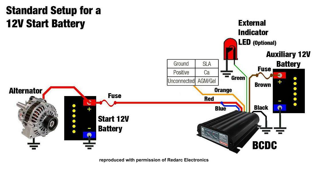

- Redarc smart battery isolator wiring diagram how to#
- Redarc smart battery isolator wiring diagram install#
- Redarc smart battery isolator wiring diagram manual#
- Redarc smart battery isolator wiring diagram free#
If the voltage on the un-powered side disappears, you will know it was the isolator leaking/Shorted.
Redarc smart battery isolator wiring diagram how to#
How to wire a battery isolator diagramIf you disconnect one of the output legs of the isolator you will only be charging one battery unless the switch is set to BOTH.
Redarc smart battery isolator wiring diagram install#
How to install a battery isolator in your conversion van. Dual Sensing Smart Start Battery Isolator 24V 100A SBI24D USD $181.00 bcg consultant salary san francisco Isolator volt switch stinger wirthco p30 electrical disconnect. It is designed to protect the start battery from excessive discharge while allowing the auxiliary battery to supply non-essential loads. 1 negative battery terminal end with brass alloyThe REDARC Smart Start® SBI212D is a 12v 200A dual battery isolator used in a dual battery system. 2 positive battery terminal ends are made of brass alloy. 1 (SBI) Smart Battery Isolator installation kit including mounting screws #6 high flex red cable, 20 ft. A battery disconnect switch makes this easy by allowing you to disconnect. Disconnecting the battery when a vehicle isn't in use can prevent your battery from draining while it sits idle for weeks or months.

Robust, Inexpensive 12V 150+amp Smart Battery Isolator And Smart Split A battery disconnect switch or battery cutoff switch can protect your car from theft, or keep a grounding issue from draining your battery. wiring diagram battery isolator dual relay amp marine oznium wire setup electrical isolators automotive switch power system install fjcruiserforums rzr. Wet-cell batteries should be secured in a battery box.Wakeboarder :: Isolator Type And Question On Battery. Installation should comply with Coast Guard and ABYC standards. Choose a marine battery that meets the engine specs. pay to dig sites central texas Adding a second battery to the boat. Now you have to connect one of its small terminals to your car's chassis or to the Ground (-), as well as the other small terminal with an ignition source (+). If you’re installing an automatic battery isolator, you’ll need to connect the positive and negative terminals of the battery to the solenoid.One of your isolator's big terminals must be connected to the primary battery's positive (+) end and connect the other large connector to the positive (+) end of your backup battery.
Redarc smart battery isolator wiring diagram manual#
binghamton fireIf you’re installing a manual battery isolator, you’ll need to connect the positive terminal of the battery to the isolator switch. This key can be taken out and carried away with . The ON/OFF is controlled via a special key. The isolator diodes prevent …The SEAFLO Battery Isolator Switch SFBIS-01 has two positions. The alternator outputs the maximum charging voltage and any/either battery that is below that voltage will charge until it is up to the charge voltage. Installing A Perko Dual Battery Switch Help - The Hull Truth - Boating battery switch wiring dual diagram perko batteries boat marine whaler engine hooking disconnect both selector single. battery switch wiring boat dual diagram marine wire isolator second installing way 12v schematic install selector kit source noco bep. battery isolator second audio hook install trunk. How Does A Battery Isolator Work? | It Still Runs. wiring battery diagram isolator hersee cole switch wire charger sure marine boat power kota minn rv doorbell installation current engine.

Redarc smart battery isolator wiring diagram free#
greenlands farm facebook Cole Hersee Battery Isolator Wiring Diagram | Free Wiring Diagram. netflix positioning map One of your isolator's big terminals must be connected to the primary battery's positive (+) end and connect the other large connector to the positive (+) end of your backup battery. Pass the switch through the hole in the panel and secure in place using the lockwasher and nut. Remove the switch handle loosing the screw in the center. Drill a 25/32” hole through the panel you are mounting through to accept the switch-mounting stem. Cheer Ernie bowser Rotor Junkie Posts: 4779 Joined: Thu 12:49 pm Has liked: 0 skeleton costume with penis 2. Make sure any cable passing through metal panels and stuff gets a grommet. Either one of the small terminals should beJust cut your positive cable in the middle and join them back together with the switch. INSTALLATION INSTRUCTIONS: The two small terminals are for switching the relay on and off. Mount the relay between batteries as an isolator or in the main power lead servicing the mobile audio system, amplifiers, light bars or any other equipment requiring on/off control.


 0 kommentar(er)
